Leave Your Message

Why Choose a Microchannel Heat Exchanger?

Choosing the right heat exchanger affects efficiency, reliability, serviceability, and operating cost. A Microchannel Heat Exchanger offers a compact approach for systems that require effective heat transfer within limited space. Its small channels create a large surface area relative to its size. This design can reduce refrigerant charge and support lighter equipment. These benefits matter in air-conditioning units, heat pumps, vehicle thermal systems, and industrial cooling packages.

Performance, however, depends on more than compact dimensions. Engineers must evaluate refrigerant selection, airflow distribution, pressure drop, corrosion exposure, and manufacturing quality. In practical installations, a blocked fin surface can reduce performance quickly. Poor header design may also create uneven flow across the core. Field experience shows that laboratory efficiency does not always equal dependable operation. That assumption needs checking.

A reliable selection process begins with measured operating conditions. Designers should compare entering temperatures, mass flow rates, allowable pressure loss, and maintenance access. Computational models can guide sizing, but testing remains essential. Prototype evaluation may reveal noise, frosting, vibration, or cleaning difficulties before full production. Material compatibility deserves equal attention, especially in coastal or chemically aggressive environments. A Microchannel Heat Exchanger is not automatically the best solution. It becomes valuable when its advantages match the system’s real constraints. Careful verification supports safer decisions, longer service life, and more predictable energy performance. Small details matter. Consistent documentation also strengthens technical confidence among manufacturers, installers, and end users.
Why Choose a Microchannel Heat Exchanger?

Microchannel Heat Exchanger: Structure and Operating Principles

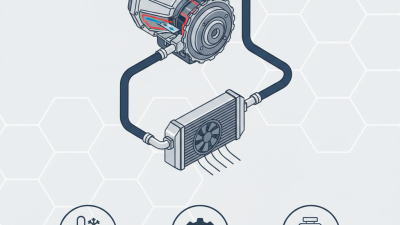
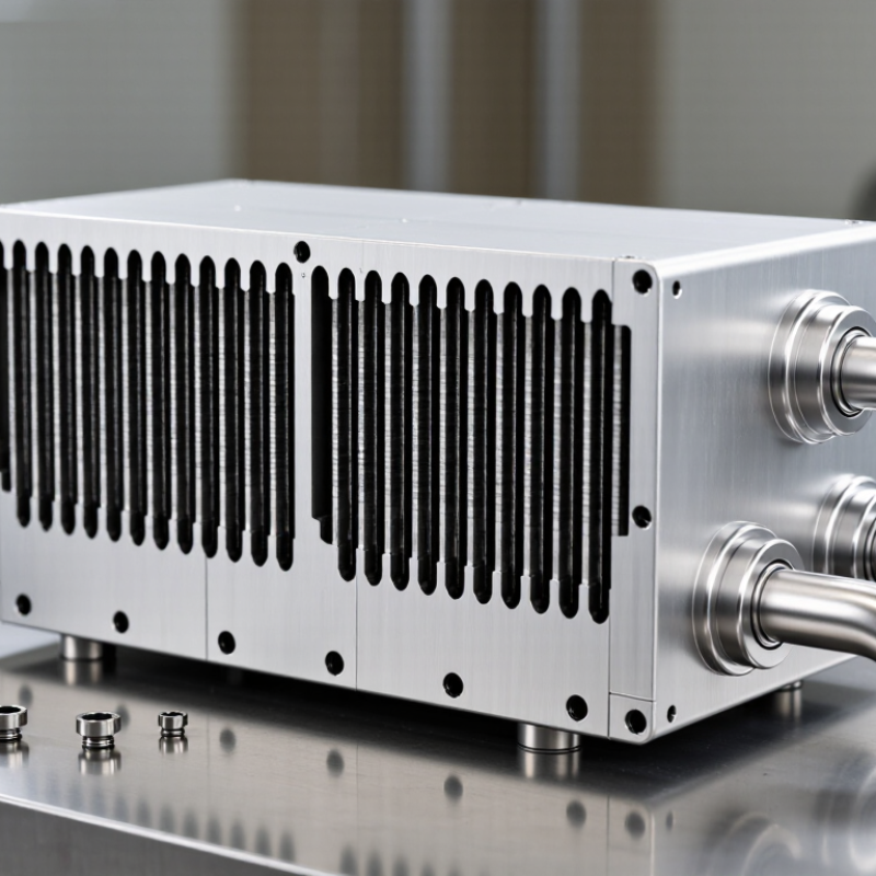
A microchannel heat exchanger uses several compact passages inside flat tubes. Thin fins connect these tubes and enlarge the air-side surface. Headers distribute fluid across the parallel channels. This structure creates a large heat-transfer area within a smaller volume. In practical equipment rooms, the reduced depth can simplify installation.

Its operating principle is straightforward.

Refrigerant or another working fluid enters one header and divides among many channels. Air moves across the finned tubes, usually from a fan or natural airflow. Heat travels through the tube walls and fins, then leaves with the air. During refrigeration, the fluid may evaporate or condense inside the channels. Flow control remains critical.

Small passages matter.

They can reduce internal fluid volume and improve thermal response. However, they also demand clean manufacturing and careful circuit design. Uneven distribution may leave some channels underused. That weakens performance. Pressure drop, fin spacing, corrosion protection, and airflow resistance require separate checks. Field inspections often reveal dust blocking the fins, even when the internal circuit works correctly.

Engineers should match the exchanger to operating temperature, fluid properties, airflow, and maintenance conditions. A compact design is not automatically the best design. In coastal or dusty locations, protective materials and accessible cleaning paths deserve close attention. I have found that performance calculations can look convincing until real airflow changes with fouling. That is an uncomfortable, but useful, limitation.


Key Advantages Over Conventional Heat Exchangers

Why Choose a Microchannel Heat Exchanger?

Microchannel heat exchangers offer clear advantages over conventional tube-and-fin designs. Their small parallel channels create more heat-transfer surface within a compact core. This can reduce equipment size, weight, and internal refrigerant volume. DOE Building Technologies Office evaluations have reported refrigerant-charge reductions of roughly 20–40% in comparable applications. That matters as cooling demand grows. The International Energy Agency’s The Future of Cooling report projects global space-cooling energy demand could more than triple by 2050.

The practical benefits appear in real equipment rooms. A smaller coil can leave more cabinet space for fans, filters, or controls. Lower material use may also simplify transport and installation. ASHRAE Handbook—HVAC Systems and Equipment, 2024, emphasizes that coil selection must balance heat transfer, pressure drop, fouling, and service access. Microchannels are not automatically better. Their narrow passages can respond poorly to blocked airflow, uneven distribution, or aggressive cleaning chemicals. I would not treat every published percentage as universal.

Design details decide the outcome. A well-selected microchannel coil can deliver strong capacity from a shallow, lightweight assembly. An unsuitable design may increase fan energy or complicate maintenance. Field technicians often notice this difference first: dust on a dense face can reduce airflow quickly. Corrosion protection, drain-pan design, and accessible cleaning paths deserve equal attention. The technology is efficient, but not effortless.

Energy Efficiency, Size, and Material-Saving Benefits

Why Choose a Microchannel Heat Exchanger?

Microchannel heat exchangers use many narrow passages to increase surface contact. This geometry transfers heat efficiently within a compact frame. In practical cooling systems, lower refrigerant volume can reduce operating costs and environmental impact. Smaller internal space also simplifies installation in crowded equipment rooms.

Less space. Lower weight.

Energy efficiency is not automatic. Engineers must match airflow, pressure drop, and operating temperature carefully. When airflow remains balanced, closely packed fins can improve heat transfer with less energy. A smaller temperature difference may reduce compressor workload. However, dust, uneven distribution, or poor maintenance can quickly weaken these gains. These details are often underestimated.

Field measurements matter.

Material savings provide another advantage. A compact core may require less aluminum while maintaining the needed heat-transfer area. Lower material use can reduce transport weight and manufacturing demand. Yet thinner channels require precise production and careful system design. Cleaning may also be less forgiving. A design that looks efficient on paper may struggle in a dusty workshop. Engineers should compare pressure drop, seasonal performance, service access, and long-term durability before selecting the exchanger.

The trade-off is real.

Performance Factors in Different Thermal Applications

Why Choose a Microchannel Heat Exchanger?
Performance Factors in Different Thermal Applications

A microchannel heat exchanger uses small internal passages to increase contact between fluid and metal. This compact structure can transfer heat efficiently with less material. In field testing, engineers often measure outlet temperature, pressure drop, airflow, and surface temperature together. One number rarely tells the whole story.

For air-conditioning systems, refrigerant distribution matters greatly. Uneven flow can leave some channels cold while others remain underused. In liquid cooling applications, water quality and flow speed affect performance. Narrow passages may improve heat transfer, but they can also become sensitive to dirt, scale, or poor filtration. Maintenance planning should begin during design, not after failure.

Electronics cooling needs a different balance. A small exchanger may fit beside a power module, yet limited airflow can reduce its real capacity. Thermal imaging can reveal hot spots near bends, joints, and blocked fins.

I have seen compact designs perform well in laboratory tests but struggle inside dusty equipment cabinets. That gap deserves attention. Engineers should test realistic air temperatures, vibration, humidity, and partial-load operation. These conditions often expose weaknesses hidden by ideal calculations.

Material selection also influences corrosion resistance, weight, and service life. Lightweight construction can support mobile equipment, but repeated thermal cycling may create stress. The best choice depends on the application, not only on maximum rated efficiency.

Selection Criteria for Microchannel Heat Exchangers

Why Choose a Microchannel Heat Exchanger?

Selection should begin with operating data, not compact appearance. A practical review starts with heat duty, fluid temperatures, flow rates, and allowable pressure drop. The IEA’s The Future of Cooling report estimates global cooling electricity demand could rise from about 2,000 TWh in 2016 to 6,200 TWh by 2050. Efficiency matters. The U.S. Department of Energy reports that HVAC systems can consume roughly 40% of energy in many commercial buildings.

Pressure drop deserves early attention. A smaller core may reduce material use, yet an overly restrictive design can increase fan or compressor power. Specify the maximum air-side and fluid-side pressure losses before comparing exchanger dimensions. Check refrigerant compatibility, working pressure, temperature cycling, and required safety margins. ASHRAE Handbook guidance also supports evaluating capacity at actual entering conditions, rather than relying on catalog ratings alone.

The installation environment changes the decision. Coastal air, dust, cleaning chemicals, and industrial moisture can accelerate corrosion or blockage. Review fin spacing, coating requirements, inspection access, drainage, and freeze protection. Consider lifecycle cost, not only purchase price. A low-cost exchanger becomes expensive when it is difficult to clean or replace. Field experience also shows a common weakness: laboratory performance does not always predict neglected maintenance. The selection may need revision after real airflow measurements, seasonal loading, and service feedback.

Why Choose a Microchannel Heat Exchanger? - Selection Criteria for Microchannel Heat Exchangers

Selection Criterion Typical Microchannel Heat Exchanger Characteristics Why It Matters Recommended Selection Guidance Key Verification Data
Required Heat Transfer Capacity Compact parallel-flow cores can provide high heat-transfer rates relative to their volume when properly sized. The exchanger must meet the design load at the required entering and leaving temperatures. Select the core from a thermal rating at the actual fluid temperatures, flow rates, refrigerant, and operating conditions—not from face area alone. Design duty, inlet/outlet temperatures, mass flow rate, and required approach temperature.
Compactness and Weight Small hydraulic passages and stacked multiport tubes allow a large heat-transfer surface in a relatively small, lightweight core. Lower equipment volume and mass can simplify installation and reduce structural requirements. Favor microchannel construction where cabinet space, vehicle weight, rooftop loading, or shipping volume is limited. Overall envelope, operating weight, dry weight, mounting points, and service clearances.
Air-Side Pressure Drop Pressure drop depends strongly on fin geometry, face velocity, depth, louver design, and surface condition. Excessive air resistance increases fan power and may reduce system airflow. Choose the smallest pressure drop that meets the heat-transfer requirement and available fan static pressure. Airflow rate, face velocity, fan curve, air-side pressure drop, and allowable fan power.
Refrigerant-Side Pressure Drop Small channels can produce efficient heat transfer, but refrigerant pressure drop must be checked carefully, especially in long or multi-pass circuits. Pressure loss affects saturation temperature, compressor lift, capacity, and energy efficiency. Use a circuit design that balances pressure drop, refrigerant distribution, and required superheat or subcooling. Refrigerant type, mass flow, circuit length, number of passes, inlet quality, and calculated pressure drop.
Refrigerant Charge The internal volume of a microchannel refrigerant circuit is often lower than that of larger-tube designs of comparable capacity. Lower charge can reduce material cost and may support systems with stricter refrigerant inventory limits. Calculate charge from internal volume and operating density; do not assume a fixed percentage reduction for every design. Internal refrigerant volume, refrigerant density, operating charge, and system receiver capacity.
Operating Pressure and Temperature Aluminum microchannel cores are commonly used in air-conditioning and refrigeration duties, subject to the approved design pressure and temperature limits. The core must safely withstand normal operation, start-up, shutdown, pressure pulsation, and abnormal conditions. Select only a design with documented pressure ratings, burst margins, and compliance for the intended refrigerant and application. Maximum working pressure, test pressure, design temperature range, refrigerant compatibility, and applicable code.
Material Compatibility Many microchannel cores use aluminum tubes, fins, and headers joined by controlled brazing processes. Material selection influences corrosion resistance, refrigerant compatibility, durability, and allowable joining methods. Confirm compatibility with refrigerant, oil, water quality, additives, cleaning chemicals, and surrounding atmospheric conditions. Alloy specifications, galvanic-corrosion risk, fluid chemistry, coating requirements, and joining process.
Corrosion and Environmental Exposure Fine fins and closely spaced passages can be sensitive to salt, dust, moisture, industrial pollutants, and chemical contamination. Corrosion or blocked fins can reduce capacity, increase pressure drop, and shorten service life. For coastal, marine, agricultural, or industrial locations, consider protective coatings, suitable fin spacing, drainage, and routine cleaning. Ambient contaminants, salt exposure, humidity, coating specification, fin spacing, and cleaning interval.
Air Cleanliness and Fouling Compact fin geometry can collect debris if filtration and maintenance are inadequate. Fouling reduces effective surface area and raises air-side resistance. Use appropriate filters, access panels, drain provisions, and cleaning methods that will not deform fins. Particle loading, filter efficiency, fin spacing, access clearance, allowable cleaning pressure, and maintenance plan.
Refrigerant Distribution Multiple parallel ports require balanced circuiting to distribute refrigerant evenly across the core. Uneven distribution can create dry-out, flooding, local temperature variation, and reduced capacity. Review distributor design, installation orientation, circuit layout, and operating range at both full and part load. Circuit map, distributor arrangement, quality distribution, orientation limits, and part-load performance.
Condensation and Drainage When used as an evaporator, condensate management depends on fin spacing, airflow direction, surface temperature, and installation angle. Poor drainage can increase air resistance, cause water carryover, and promote corrosion or microbial growth. Provide suitable slope, drain pans, separators where necessary, and adequate clearance for condensate removal. Condensate rate, fin geometry, airflow direction, drain-pan design, installation angle, and carryover limit.
Manufacturing and Quality Control Performance depends on accurate port geometry, uniform brazed joints, clean internal passages, and consistent circuiting. Manufacturing variation can affect leakage risk, pressure drop, thermal performance, and long-term reliability. Require documented leak testing, pressure testing, cleanliness control, dimensional inspection, and thermal-performance validation. Leak-test method, pressure-test record, cleanliness standard, brazing controls, inspection records, and sample performance data.
Serviceability and Repair The compact core is generally not designed for routine internal disassembly; damaged tubes or headers may require specialized repair or replacement. Maintenance strategy affects lifecycle cost and system availability. Allow access for coil cleaning, leak inspection, fin straightening, refrigerant recovery, and component replacement. Access dimensions, repair procedure, spare-part availability, cleaning instructions, and expected service interval.
Life-Cycle Cost and Efficiency Potential benefits include compact packaging, lower material use, and efficient heat transfer; actual savings depend on system design and operating conditions. Initial purchase cost alone does not reflect fan energy, compressor energy, maintenance, refrigerant, and replacement costs. Compare complete-system performance over the expected operating life rather than comparing exchanger purchase prices only. Seasonal efficiency, fan power, compressor power, refrigerant charge, maintenance cost, and service life.

Note: Performance values and pressure ratings are application-specific. Final selection should be based on validated thermal, hydraulic, mechanical, environmental, and regulatory data for the complete operating envelope.